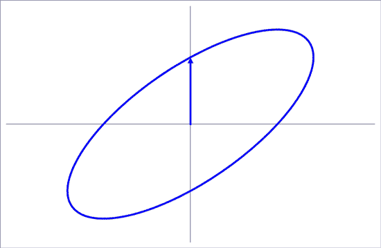
When there is just a single source of magnetic field, the field oscillates backwards and forwards along a straight line. But where there is more than one source of field at the same frequency, the magnetic field traces out an ellipse in space. The orientation and shape of the ellipse depend on the details of the sources.
The mathematics that generates an ellipse
Mathematically, you get an ellipse when the vertical and horizontal components of the field have different phases. You can explore the effect of setting different phases and amplitudes in this tool (type values into the white cells - it will reject any changes typed anywhere else):
Note: this tool is hosted on the Cloud. If you do not see the drawing, but get a message "proxy server is refusing connections", this probably means that Cloud services are barred by your internet service. Contact us if you would particularly like to see this tool. The full functionality is supported only for desktops and laptops - mobile devices may not allow all the interactivity.
Defining the size of the field
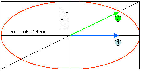
The red ellipse in this diagram shows the ellipse traced out by the magnetic field over the course of one cycle.
The largest value obtained by the field is along the major axis (or long axis) of the ellipse. This is defined as the maximum field. Arrow 1 shows the root-mean-square (rms) of the component of the field along this direction.
Arrow 2 has a particular property: because of the geometry of ellipses, the length of arrow 2 gives the rms of the magnetic field, known as the resultant field. This is the normal way of describing an elliptically polarised field.
And yes, we do all realise how daft it is that the "maximum" field is actually smaller than the "resultant" field...
Measuring elliptically polarised fields
If you take a single-axis meter (e.g. a single coil) and rotate it until it gives the maximum reading, it will be measuring the field along the direction of arrow 1. Assuming the meter is calibrated to give the rms, it will measure arrow 1: the maximum field.
If you take a three axis meter (ie three coils at right angles to each other), you don’t need to rotate it. Whatever orientation it is in relative to the field, it will give arrow 2: the resultant field. (Most meters do this by recording the rms of the field in each of the three directions, then adding these by root-sum-of-squares. This gives the same answer as measuring the rms directly.)
The extreme cases
As the ellipse gets more and more squashed, arrows 1 and 2 become more and more similar. In the limit of a linearly polarised field, they are the same.
The other extreme is when the ellipse becomes a circle. For circularly polarised field, the resultant (arrow 2) is bigger than the maximum field (arrow 1) by a factor of the square root of 2, about 1.4 times.
Elliptical polarisation under power lines
Magnetic fields at large distances from a single circuit where all the conductors lie in a straight line are linearly polarised. At closer distances or if the conductors aren't in a straight line or if there are two circuits, the magnetic field is elliptically polarised. We provide examples of ellipses from several different configurations of power lines here.
Electric fields
Electric fields can also be elliptically polarised. But under power lines, close to the ground, they tend to be vertical and nearly linearly polarised. You can find the actual numbers relating to this on our page of ellipses from power lines.
see also: