EMFs.info

Electric and magnetic fields and health

index/glossary | EMFs At A Glance | EMF The Facts (pdf)
  • What are EMFs
    • Terminology – an introduction
    • Electric fields
    • Magnetic fields
    • Units for measuring EMFs
    • Measuring and calculating EMFs
      • “EMF Commercial”
    • Adding fields together
    • Radiofrequencies
    • Screening EMFs
  • Sources
    • Overhead power lines
      • Fields from specific power lines
        • 400 kV
        • 400 kV – specific cases
        • 275 kV
        • 132 kV
        • 66 kV
        • 33 kV
        • 11 kV
        • 400 V/230 V
        • Replacing a 132 kV line with a 400 kV line
      • Summaries of fields from all power lines
      • Factors affecting the field from a power line
        • Voltage
        • Current
        • Clearance
        • Height above ground
        • Conductor bundle
        • Phasing
        • Balance between circuits
        • Balance within circuit
        • Ground resistivity
        • Two parallel lines
      • Calculating and measuring fields from power lines
        • Geometries of power lines
        • Raw data
        • On-line calculator
      • Fields from power lines – more detail on the physics
        • Field lines from a power line
        • The direction of the field from a power line
        • Power law variations in the field from a power line
      • Statistics of power line fields
    • Underground power cables
      • Different types of underground cable
      • Fields from cables in tunnels
      • Gas Insulated Lines (GIL)
      • Underground cables with multiple conductors
      • Effect of height on fields from underground cables
      • Screening fields from underground cables
    • Low-voltage distribution
      • UK distribution wiring
      • USA distribution wiring
    • House wiring
    • Substations
      • National Grid substations
        • Static Var Compensators
      • Sealing-end compounds
      • Distribution substations
      • Final distribution substations
        • Indoor substations
    • Transport
      • EMFs from electric trains (UK)
      • EMFs from cars
    • Appliances
    • Electricity meters
      • Smart meters
      • Traditional meters
    • Occupational exposures
      • Live-line work
      • Static Var Compensators
      • Occupational exposures on pylons
    • Field levels and exposures
      • Personal exposure
      • Other factors that vary with magnetic fields
      • Fields greater than 0.2 or 0.4 µT
    • Screening EMFs
      • Screening fields from underground cables
      • EMF Reduction Devices
  • Known effects
    • Induced currents and fields
    • Microshocks
      • Control of microshocks in the UK
      • Microshocks from bicycles
      • Bees and microshocks
    • EMFs and medical devices
      • Standards relating to pacemakers and other AIMDs
    • Effects of EMFs on equipment
  • Research
    • Types of research
    • Epidemiology
    • Animal and laboratory experiments
    • Mechanisms
    • Specific studies
      • UKCCS
      • CCRG
      • French Geocap study
      • CEGB cohort
      • Imperial College study
  • Current evidence on health
    • Childhood leukaemia
      • Survival from childhood leukaemia
      • Childhood leukaemia and Downs
      • Childhood leukaemia and night-time exposure
      • The “contact current” hypothesis
    • Other health effects
    • Scientific review bodies
      • WHO
      • IARC
    • Electric fields and ions
    • Comparing EMFs to other issues
  • Exposure limits for people
    • Limits in the UK
    • Limits in the EU
    • Limits in the USA
    • Limits in the rest of the world
    • Limits from specific organisations
      • ICNIRP 1998
      • ICNIRP 2010
      • NRPB 1993
      • NRPB 2004
      • EU 2004
      • EU 2013
  • Policy
    • UK policy
      • Power lines and property – UK
    • Compliance with exposure limits
    • European EMF policy
    • Precaution
    • SAGE
      • SAGE First Interim Assessment
        • Government response to SAGE First Interim Assessment
      • SAGE Second Interim Assessment
        • Government response to SAGE Second Interim Assessment
        • SAGE Second Interim Assessment – the full list of recommendations
  • Finding out more
    • EMF measurement and commercial services
    • Links
    • Literature
    • Contact us
  • Static fields
    • Static fields – the expert view
You are here: Home / Sources / Overhead power lines / Factors affecting the field from a power line / Clearance

Clearance

How the clearance affects the field produced by an overhead line

The actual field produced by an overhead line depends on several factors. This page illustrates this for one standard line, a 400 kV L12 transmission line with typical loads. Our detailed calculations of fields all specify the conditions they were calculated for.

Both electric and magnetic fields depend on the clearance of the line. The minimum ground clearance of a 400 kV line is 7.6 m, dropping to 5.2 m for low-voltage distribution lines.  See a full listing of minimum clearances for high-voltage lines under different circumstances. But in reality it is rare for lines to be this low, and the ground-level field falls rapidly with the height of the line above ground.

Magnetic field

The maximum fields that are produced by a line occur directly underneath the line, underneath the lowest point of the conductors, which is usually towards the middle of each span. Actual conductor clearances above ground would generally be higher than this (and therefore the fields produced near ground level would be lower) for two main reasons. Firstly, for most of the length of a span, the conductor clearance is higher than it is at the lowest point. Secondly, the actual ground clearance of the conductors depends on their temperature. For the vast majority of the time they operate at less than their rated maximum temperature and therefore sag less, resulting in higher ground clearances.

graph showing how magnetic field depends on clearance


This graph shows the clearance makes more difference close to the line.  Because the maximum field depends so much on the clearance, fields expressed as a percentage of the maximum can be misleading - see more details below.

Electric field

The maximum fields that are produced by a line occur directly underneath the line, underneath the lowest point of the conductors, which is usually towards the middle of each span. Actual conductor clearances above ground would generally be higher than this (and therefore the fields produced near ground level would be lower) for two main reasons. Firstly, for most of the length of a span, the conductor clearance is higher than it is at the lowest point. Secondly, the actual ground clearance of the conductors depends on their temperature. For the vast majority of the time they operate at less than their rated maximum temperature and therefore sag less, resulting in higher ground clearances.

We give two graphs here to illustrate the effect.  Both are for 400 kV lines as these produce the highest electric fields.  The first shows the electric field for three representative designs of UK power line with their respective standard conductor bundle.  The lower group of solid lines are for the common transposed phasing, the upper group of dotted lines for the much rarer untransposed phasing, which produces higher fields.

graph showing how electric field varies with line type 

The second graph takes just one of these line types, the L6, and shows the effect of different conductor bundles. (The field from the smaller of the two quad bundles is almost identical to that from the triple bundle so the lower of the two red lines and the green line are practically superimposed on each other.)

 graph showing how electric field depends on bundle

These graphs can be used, for example, to read off what clearance is required to achieve compliance with electric-field exposure limits. We also provide a table giving the result below.

The details:

Quad bundles: zebra conductors.  L6 twin and triple: araucaria conductors.  L2 twin: zebra conductors.  The field from triple bundles may depend on the orientation of the triangle.  L6 lines were mostly built in the 1960s with a quad bundle spaced at 305 mm, but many have subsequently changed to a larger spacing of quad (400 mm or the 500 mm we illustrate here), or to twin, or, more recently, triple.  New lines are likely to be triple conductors on a tower design similar to the L12.

Clearances required for field to be below 9 kV/m for 400 kV lines

We discuss above the effect of the clearance of the conductors above ground on the electric field.  The higher the clearance, the lower the field.  Because the electric field exposure limit for the general public in populated areas in the UK is 9 kV/m, we list here the clearances required for the field to be below 9 kV/m.  If the clearance is greater than the stated value, the electric field will be below 9 kV/m.

The field depends on several factors as shown in the table: the tower design, the conductor bundle, and the phasing (transposed, T, or untransposed, U - other phasings lie between these values).


towerconductor bundlephasing
number of conductorsconductor typespacingTU
L13tripleAraucaria500 mm8.4 m9.3 m
L12twinAraucaria500 mm7.8 m8.8 m
Redwood500 mm7.9 m8.9 m
triple (pointing sideways)Araucaria500 mm8.3 m9.7 m
L8twinRubus400 mm7.5 m8.5 m
Sorbus400 mm7.6 m8.5 m
Matthew400 mm7.5 m8.5 m
L6(M)quadZebra305 mm square8.5 m9.2 m
500 mm horizontal
300 mm vertical
8.7 m9.5 m
500 mm square (L6(M), BICC and BB)8.9 m9.8 m
500 mm square (BK and JLE)8.8 m9.9 m
triple (pointing sideways)Araucaria500 mm8.4 m9.1 m
triple (pointing down)Araucaria500 mm8.3 m9.1 m
twinAraucaria500 mm8.0 m8.5 m
Redwood500 mm8.1 m8.6 m
L2twinZebra305 mm7.2 m8.3 m
Rubus500 mm7.5 m8.8 m
Rubus400 mm7.4 m8.6 m
Sorbus400 mm7.4 m8.6 m
Matthew400 mm7.4 m8.6 m

All calculations for 400 kV, 1 m above ground level, and using the infinite-straight-line approximation in accordance with the Code of Practice on demonstrating compliance.  Clearances are at 0.1 m resolution (the first 0.1 m increment of extra clearance needed to reduce the field below 9 kV/m, not the nearest 0.1 m).

Different ways of presenting the effect of clearance

This graph shows the way the field falls with distance for two different clearances of the line above ground. As expected, close to the line, the lower clearance produces the higher field.graph showing effect of clearance

This graph shows exactly the same data but presented as percentage of the maximum field for each case rather than as the actual field value. This makes it look as if one field is falling much more rapidly with distance than the other, but this is just a consequence of plotting as a percentage rather than as the actual value.

graph showing effect of clearance as percentage 

Fields presented as percentages of the maximum have sometimes been used to suggest the calculations are unreliable because the field falls too rapidly, but this comparison is not valid unless the clearances are the same in each case.

See also:

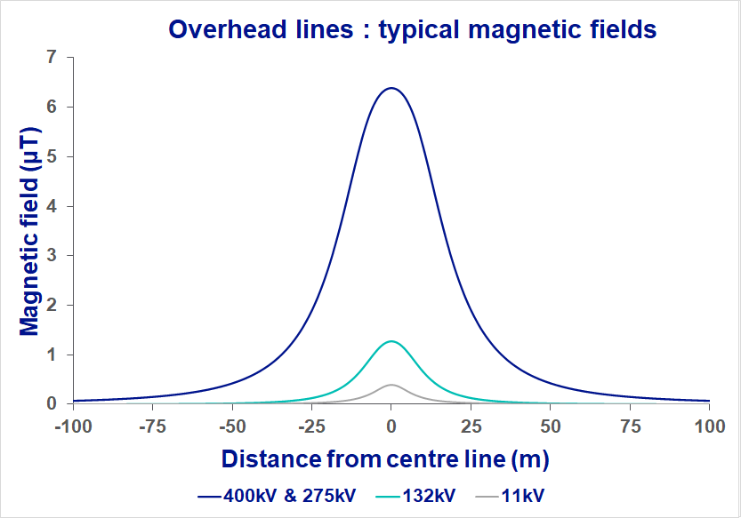
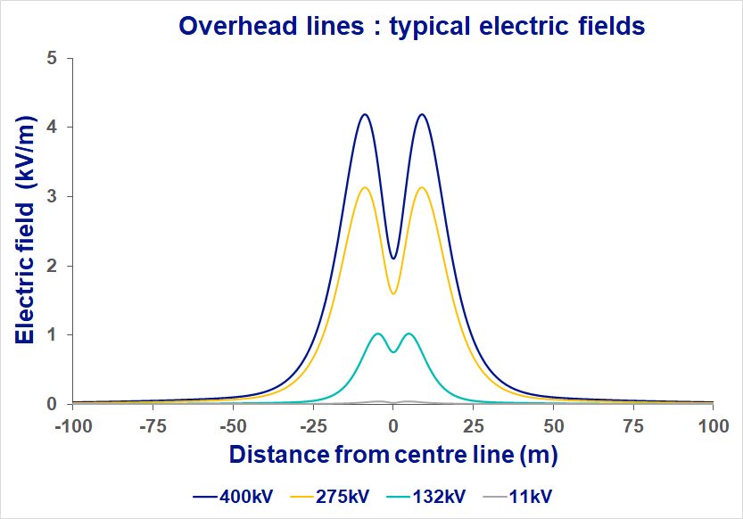
  • The fields from the different voltages of power lines
  • These pages deal with the size of the field - see also the direction of the field

Latest news

  • New publication on cancer incidence from the UK electricity industry Cohort Study August 27, 2019
  • How has the reported risk for childhood leukaemia changed over time? February 11, 2019
  • Media stories about microshocks in children’s playground September 10, 2018
  • New studies on leukaemia and distance from power lines June 1, 2018
older news

Contact Us

To contact the electricity industry’s EMF Unit Public Information Line (UK only):
telephone 0845 7023270 or email [email protected].

See Contact us for more contact details including our privacy policy.

About this site

  • What this site covers and what it doesn’t
  • Industry policy
  • Sitemap

Specific questions

  • Affected by a new power line or substation?
  • Building or developing near a power line or substation?
  • EMF measurement and commercial services
  • Microshocks
  • Pacemakers and other medical devices
  • EMF policy in the UK
Site Authorship |Sitemap | Terms and Conditions | Privacy Policy | Cookies | Site Statistics
© 2021 EMFS.info
Navigation
  • What are EMFs
    • Terminology – an introduction
    • Electric fields
    • Magnetic fields
    • Units for measuring EMFs
    • Measuring and calculating EMFs
      • “EMF Commercial”
    • Adding fields together
    • Radiofrequencies
    • Screening EMFs
  • Sources
    • Overhead power lines
      • Fields from specific power lines
        • 400 kV
        • 400 kV – specific cases
        • 275 kV
        • 132 kV
        • 66 kV
        • 33 kV
        • 11 kV
        • 400 V/230 V
        • Replacing a 132 kV line with a 400 kV line
      • Summaries of fields from all power lines
      • Factors affecting the field from a power line
        • Voltage
        • Current
        • Clearance
        • Height above ground
        • Conductor bundle
        • Phasing
        • Balance between circuits
        • Balance within circuit
        • Ground resistivity
        • Two parallel lines
      • Calculating and measuring fields from power lines
        • Geometries of power lines
        • Raw data
        • On-line calculator
      • Fields from power lines – more detail on the physics
        • Field lines from a power line
        • The direction of the field from a power line
        • Power law variations in the field from a power line
      • Statistics of power line fields
    • Underground power cables
      • Different types of underground cable
      • Fields from cables in tunnels
      • Gas Insulated Lines (GIL)
      • Underground cables with multiple conductors
      • Effect of height on fields from underground cables
      • Screening fields from underground cables
    • Low-voltage distribution
      • UK distribution wiring
      • USA distribution wiring
    • House wiring
    • Substations
      • National Grid substations
        • Static Var Compensators
      • Sealing-end compounds
      • Distribution substations
      • Final distribution substations
        • Indoor substations
    • Transport
      • EMFs from electric trains (UK)
      • EMFs from cars
    • Appliances
    • Electricity meters
      • Smart meters
      • Traditional meters
    • Occupational exposures
      • Live-line work
      • Static Var Compensators
      • Occupational exposures on pylons
    • Field levels and exposures
      • Personal exposure
      • Other factors that vary with magnetic fields
      • Fields greater than 0.2 or 0.4 µT
    • Screening EMFs
      • Screening fields from underground cables
      • EMF Reduction Devices
  • Known effects
    • Induced currents and fields
    • Microshocks
      • Control of microshocks in the UK
      • Microshocks from bicycles
      • Bees and microshocks
    • EMFs and medical devices
      • Standards relating to pacemakers and other AIMDs
    • Effects of EMFs on equipment
  • Research
    • Types of research
    • Epidemiology
    • Animal and laboratory experiments
    • Mechanisms
    • Specific studies
      • UKCCS
      • CCRG
      • French Geocap study
      • CEGB cohort
      • Imperial College study
  • Current evidence on health
    • Childhood leukaemia
      • Survival from childhood leukaemia
      • Childhood leukaemia and Downs
      • Childhood leukaemia and night-time exposure
      • The “contact current” hypothesis
    • Other health effects
    • Scientific review bodies
      • WHO
      • IARC
    • Electric fields and ions
    • Comparing EMFs to other issues
  • Exposure limits for people
    • Limits in the UK
    • Limits in the EU
    • Limits in the USA
    • Limits in the rest of the world
    • Limits from specific organisations
      • ICNIRP 1998
      • ICNIRP 2010
      • NRPB 1993
      • NRPB 2004
      • EU 2004
      • EU 2013
  • Policy
    • UK policy
      • Power lines and property – UK
    • Compliance with exposure limits
    • European EMF policy
    • Precaution
    • SAGE
      • SAGE First Interim Assessment
        • Government response to SAGE First Interim Assessment
      • SAGE Second Interim Assessment
        • Government response to SAGE Second Interim Assessment
        • SAGE Second Interim Assessment – the full list of recommendations
  • Finding out more
    • EMF measurement and commercial services
    • Links
    • Literature
    • Contact us
  • Static fields
    • Static fields – the expert view