Distribution overhead lines
Here we discuss distribution voltage, by which we mean all voltage at 132 kV and below, although in Scotland 132 kV may be classed as transmission voltage. Distribution overhead lines are at lower voltages than transmission lines and are used for distributing electricity around a local area. Some distribution overhead lines are still on steel pylons, but many are on wood poles. Nearly all these overhead lines are owned and operated by the local electricity distribution network operator.
If you live or are buying a home near to one of these types of overhead lines, below are examples of the electric and magnetic fields they produce.
As explained on the ‘What are EMFs’ page, the voltage of an overhead line is fixed, so the electric field is nearly always constant. Magnetic fields are different; they can increase or decrease depending on the current the overhead line is carrying at any time. Because of this, we provide typical levels of magnetic field that you would expect to measure from these types of overhead lines on any given day. We also provide the maximum magnetic field that each overhead line could produce if it was carrying its maximum current, however, these levels of magnetic field rarely, if ever occur.
To help identify what voltage an overhead line is operating at, please see the ‘What is near me?’ page. Once you have identified the voltage, the graphs below will give the typical day-to-day EMF exposures that an overhead line produces.
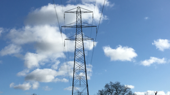
Overhead lines operating at 132 kV can come in a variety of designs. The largest 132 kV overhead lines are on steel pylons with six sets of wires. Below are the typical fields that the largest 132 kV overhead lines produce.
Magnetic fields
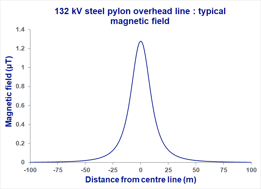
This is the typical magnetic field that a 132 kV overhead line produces. The maximum field is always directly under the wires and reduces as you move away from them.
The magnetic field directly under the wires typically ranges between 0.5 - 2 µT.
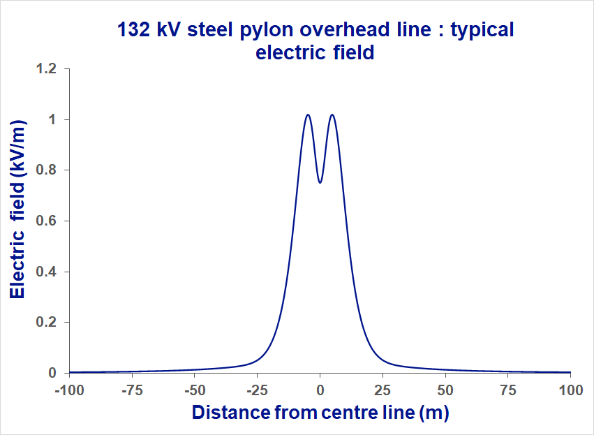
Electric fields
This is the typical electric field that a 132 kV overhead line produces. The maximum field is always directly under the wires and reduces as you move away from them.
The electric field directly under the wires is around 1 kV/m.
Typical fields table
Here are the typical electric and magnetic field values for a 132 kV steel pylon overhead line.
| 132 kV | Directly under line | 50 m from centre line | 100 m from centre line |
|---|---|---|---|
| Magnetic field | 1.3 μT | 0.03 μT | <0.01 μT |
| Electric field | 1.1 kV/m | 0.01 kV/m | <0.01 kV/m |
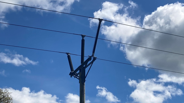
Overhead lines operating at 132 kV can come in a variety of designs. Often these are installed on wood poles with three wires arranged horizontally at the top of the pole. These are the typical fields that 132 kV wood pole overhead lines produce.
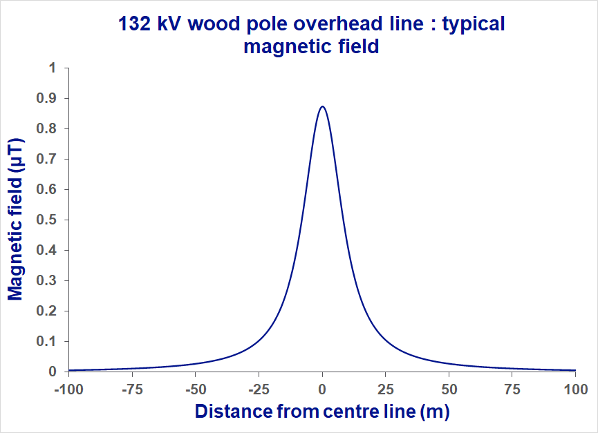
Magnetic fields
This is the typical magnetic field that a 132 kV wood pole overhead line produces. The highest field is always directly under the wires and reduces as you move away from them.
The magnetic field directly under the wires typically ranges between 0.5 - 1 µT.
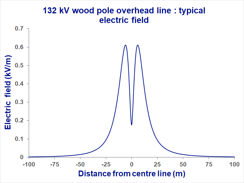
Electric fields
This is the typical electric field that a 132 kV wood pole overhead line produces. The maximum field is always directly under the wires and reduces as you move away from them.
The electric field directly under the wires is around 0.6 kV/m.
Typical fields table
Here are the typical electric and magnetic field values for a 132 kV wood pole overhead line.
| 132 kV | Directly under line | 50 m from centre line | 100 m from centre line |
|---|---|---|---|
| Magnetic field | 1 μT | 0.03 μT | <0.01 μT |
| Electric field | 0.6 kV/m | 0.02 kV/m | <0.01 kV/m |
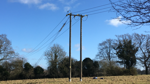
11 kV lines are either carried on small lattice steel pylons or on wood poles. There are many different variants of the overhead lines designs.
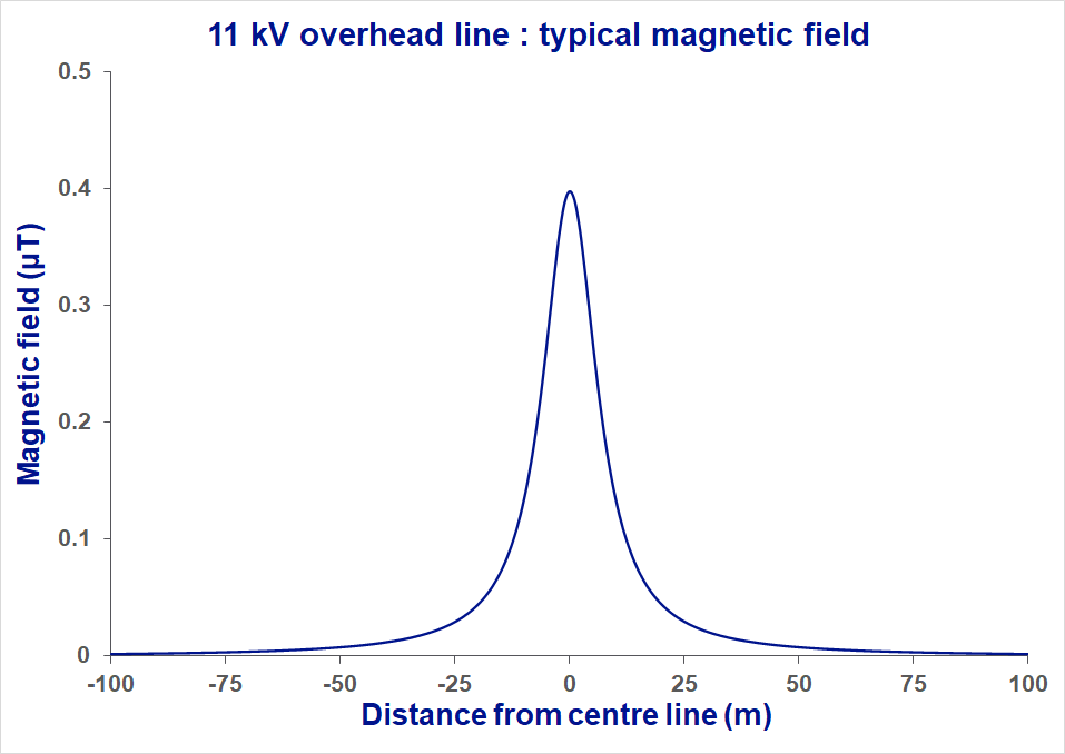
Magnetic fields
The magnetic fields from 11 kV overhead lines are small and localised. The magnetic field directly under the wires is approximately 0.4 µT, but reduces very quickly as you move away from the wires.
Electric fields
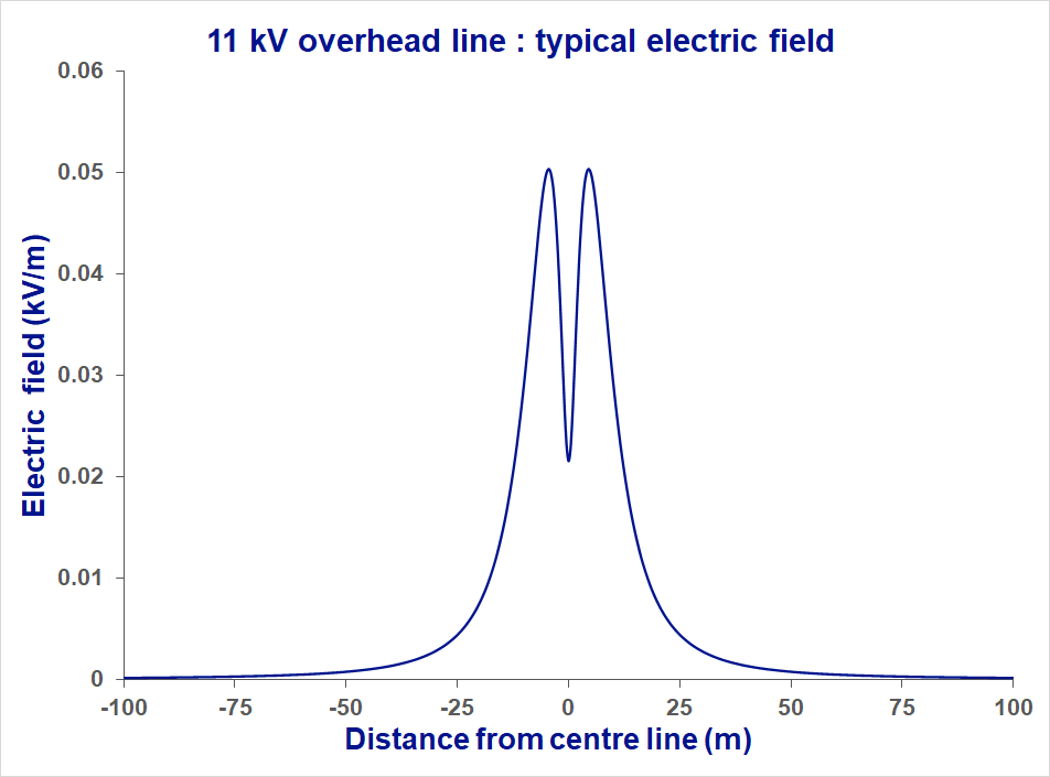
The electric fields from these overhead lines are very small, almost at a background level even under the wires. The electric field directly under the wires is around 0.05 kV/m.
Typical fields table
Here are the typical electric and magnetic field values for a 11 kV wood pole overhead line.
| 11 kV | Directly under line | 50 m from centre line | 100 m from centre line |
|---|---|---|---|
| Magnetic field | 0.4 μT | 0.008 μT | 0.002 μT |
| Electric field | 0.05 kV/m | 0.001 kV/m | 0 kV/m |
The graphs and detail above give the types of magnetic field exposures you would normally expect from overhead lines operating at these voltages. However, they have the capacity to carry more current, although this rarely occurs. Extra capacity is needed on lines to account for when another overhead line is out of service. There is also additional allowance for faults that might occur at the same time. The table below gives the maximum magnetic field that an overhead line could produce if it was operating at 100 % of its daily current capacity. The table demonstrates that, even if this were to occur, the magnetic fields would still be complaint with the public exposure limits.
| Maximum under overhead line | 50 m from centre line | 100 m from centre line | |
|---|---|---|---|
| 132 kV steel pylon overhead line | 38 µT | 1.9 µT | 0.5 µT |
| 132 kV wood pole overhead line | 12.5 µT | 0.2 µT | 0.05 µT |
| 11 kV overhead line | 9.5 µT | 0.4 µT | 0.1 µT |
| Magnetic field public exposure limit |
360 µT |
||