Most calculations of the magnetic fields from overhead power lines or from underground cables are based on what we often call the "infinite straight line approximation". As it says on the tin, we assume that the conductors are infinitely long, straight, and parallel. And that's a pretty good approximation most of the time. Overhead lines are generally straight with only occasional bends, and although the conductors sag in a curve between pylons, if you simply take the height of the conductors above ground at the point you are interested, that gives a reasonable approximation.
All the calculations of fields from overhead lines and underground cables on this site are performed using the infinite-straight-line approximation. And the Code of Practice on demonstrating compliance with exposure limits in the UK specifies that calculations should be performed in this way.
The alternative is to model the actual shape of the conductors (including the sag and any changes of direction) using a series of short, finite, straight lines - as many of these straight lines as you need to model the actual curve as accurately as you want. We often call that calculation a "3D" calculation and the infinite-straight-line calculation a "2D" calculation.
We consider below three specific situations where you might think the "infinite straight line" approximation is indeed approximate - one for an overhead line and two for underground cables - and compare the 2D and 3D calculations to see how accurate the 2D calculation actually is.
Taking account of sag in overhead lines
Overhead lines sag between the pylons (technically speaking, the shape is a "catenary", though usually a parabola is a good-enough approximation). That means the clearance of the conductors above ground varies along the length of each span.
To perform a 2D, infinite-straight-line approximation, calculation, we just take the clearance of the conductors at the point of interest and assume that the conductors are infinitely long straight lines at that height.
This is usually a pretty good approximation. This was investigated in detail as part of the comparison of calculated and measured fields. The following graph (scanned from the published paper, so apologies for the quality) shows the discrepancy between 2D and 3D calculations:
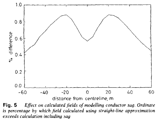
You can see that to the sides of the line, the discrepancy drops towards zero. That makes sense, because as you get further away from the line, the clearance of the conductors makes less and less difference anyway. Directly under the line, where the difference is greatest, it was still less than 1%. (This was about half way from the pylon to the middle of the span - but actually, the difference gets less as you go towards the middle.)
Horizontal Directional Drilling for underground cables
Underground cables, when they are laid direct in the ground rather than in tunnels, are generally laid as the three separate phase conductors spaced typically 0.5 m apart in flat formation at the bottom of a trench. That is an ideal situation for modelling using the infinite-straight-line approximation.
Sometimes, e.g. to go under an obstacle such as a river, we use a technique called Horizontal Directional Drilling (HDD). That means the three conductors separate out a bit and each is laid in a separate duct that curves gently downwards to get under the obstacle. Once they are in those three separate ducts, any changes of direction are very gentle, so the infinite-straight-line approximation still works well, using whatever separation and depth the cable has reached at the point of interest.
But to have space to do the drilling and installing, the three conductors have to be further apart - typically 5 m rather than the 0.5 m of the trench. So there is a transition zone where the spacing widens out (and usually the depth increases slightly). In that zone, where the conductors are diverging, it is less obvious that the 2D infinite-straight-line approximation will still work well enough.
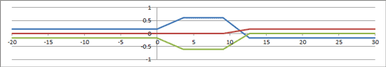
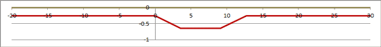
To test this, we compare the 2D (infinite straight line) and 3D calculations for one particular typical geometry of the transition to HDD. The 2D calculation uses the spacing and depth of the conductors appropriate to the point the calculation is being performed for. You can see here a plan and a profile to show the geometry, then a comparison of the 2D and 3D calculations. From -20 m to 0 m, the conductors are in the standard trench. From 0 to 10 m, they are diverging to the start of the HDD. From 10 m onwards, they are in the HDD, diverging very slightly further and gaining in depth.
Plan
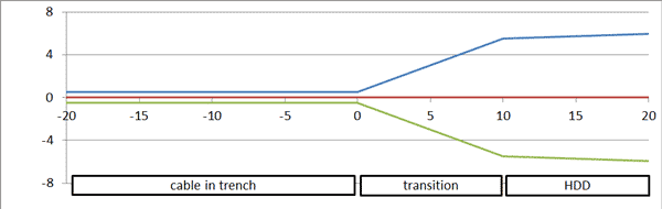
Profile
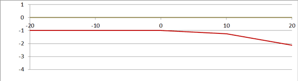
You can see that the 2D calculation - the one we normally present, based on the infinite-straight-line approximation - is actually pretty good, mostly being within a few percent of the true 3D calculation. And where the divergence is greatest, in the trench just before the transition starts, the fields are lower anyway.
Within the sort of accuracy we normally work with, the conclusion is that you can carry on using the 2D calculation quite satisfactorily.
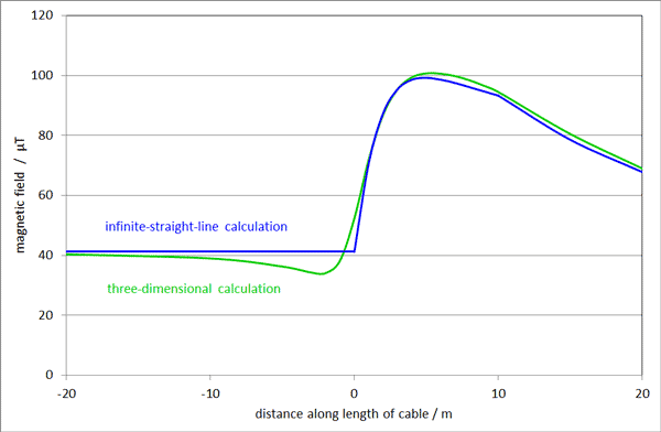
Joint bays in underground cables
Where joints are needed in underground cables (roughly every 300 m or so - it's limited by how much conductor you can fit onto one lorry load), the individual conductors usually spread apart a bit into a joint bay to give space to make the joints. So this is another instance where you might think the 2D calculation breaks down, because the conductors are no longer straight and parallel.
To see how big an effect this is, we model the fields for a pretty extreme case. We've chosen a trough installation, because that's where the conductors are normally closest together, so the difference that the joint bay makes is biggest. The plan and profile below show how the conductors widen out and go deeper for the joint (note that the vertical scale is much exaggerated compared to the horizontal scale so it makes the angles look worse than they are):
Plan
Profile
This graph shows the full, three-dimensional calculation of the field on the centreline as it goes from the cable in the trough, over the joint bay, and back into the cable in a trough. We compare it to two two-dimensional calculations, one for the spacing of the conductors in the trough, and the other for the spacing at the joint.
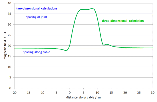
We can see that the two-dimensional calculations - assuming that the cables are infinitely long and straight - is pretty good. It gives exactly the right answer for the trough, except very close to the joint, and it gives close to the right answer for the joint bay. But where you are close to the transition sections where the cables are diverging, the field can actually drop below the first two-dimensional calculation and go above the second.
Note: the plan shows one conductor swapping over position after the joint. In most cables installations, this happens at every joint, so that, over the whole length of the cable, each conductor spends the same time in each of the three positions. It helps stop induced voltages building up and is called "transposition" - not to be confused with the phase transposition we usually talk about with overhead l;ines. It's that swapping-over of conductors that accounts for the little blip in the field at that point.