It is quite easy to measure magnetic fields. Instruments are usually based on search coils (though other types exist as well) and can be small and handheld, or larger and more sophisticated. Measuring electric fields is possible too but harder because the person making the measurement often perturbs the field. Calculations of EMFs are also easy for sources (like overhead lines and underground cables) that have clearly defined geometries.
measuring fields - simple version
Measurement of electric and magnetic fields
This is a summary of instruments for measuring fields. A more detailed technical description of the issues is also available in the next toggle below.
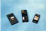
The first commercial instruments designed specifically for measuring power-frequency fields became available in the 1980s. There are now many instruments available, which vary in the number of axes they measure, how sophisticated the electronics are, whether they record fields, and whether they are meant for survey use or as a personal monitor.
There is no “correct” or “best” meter. The best meter to use depends on the purpose it is to be used for.
Measuring magnetic fields
There are three different sensors widely used for measuring magnetic fields: search coils, fluxgate magnetometers, and Hall-effect devices.
 Most practical instruments for power frequencies use search coils, either a single coil or three orthogonal coils. The coils themselves can either be made as small as possible, for use in personal exposure meters where size and weight are important criteria, or they can be larger, often 0.1 m across, to increase sensitivity and provide some spatial averaging.
Measuring electric fields
 Meters for electric fields usually use as sensors two parallel conducting plates. Alternative sensors, e.g. based on rotation of polarised light, are less common.
Three-axis electric-field meters are available, but single-axis meters are more common.
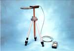
A person holding an electric-field meter would perturb the field. To measure the unperturbed field, the meter is usually held at the end of a long non-conductive horizontal rod or a vertical tripod. This can reduce perturbation to acceptable levels, but care is still needed to get accurate readings. More on how to do accurate readings
Personal exposure meters do exist for electric fields. However, wearing a meter on the body perturbs the electric field being measured in unpredictable ways.
measuring fields - more technical version
Measurement of electric and magnetic fields
This is a fairly technical account of measurement principles - for a simpler version see the previous toggle.
The first commercial instruments designed specifically for measuring power-frequency fields became available in the 1980s. There are now many instruments available, which vary in various characteristics:
(a) Number of axes of detection. There are no sensors that directly assess a resultant field in a random direction in space; sensors generally measure the field in one direction. A meter may have one sensor. If this is aligned by the user with the direction of maximum field it will give a reading of the maximum field in a single direction; the overall resultant field may be between 1.0 and 1.41 times this value depending on the degree of polarisation. If the meter has three orthogonal sensors, the resultant field can be obtained from the three values measured by root-sum-of-squares addition: Resultant = (X2+Y2+Z2)1/2 .
This resultant value is independent of the orientation of the meter, vastly simplifying use of the meter.
More on elliptically polarised fields
(b) Measure of field. Various measures of a sine wave are possible, e.g. peak, rectified average, root-mean-square (rms). For a single frequency, i.e. a pure sine wave, these can be scaled to give the same result, but in the presence of harmonics they can differ considerably. In the absence of a known biophysical mechanism, there is no conclusive basis for asserting that any one measure is correct. However, by analogy with other areas of measurement science, there is an assumption that rms is the preferred measure. Some meters capture the actual waveform for future analysis.
(c) Frequency response. Instruments may be sensitive to a single frequency e.g. 50 Hz or 60 Hz or to a range of frequencies. If sensitive to a range of frequencies, the response may be flat or may be proportional to frequency. A flat frequency response between 20 or 30 Hz and a few kiloherz is generally regarded as suitable for many general purpose measurements.
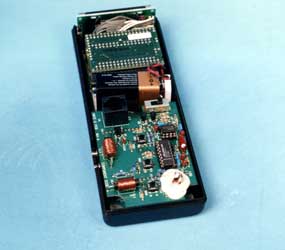
(d) Size of sensors. Sensors can be made small – a few millimetres - and therefore capable of investigating variations of field over small distances. However, there may also be times when it is desirable to use larger sensors which measure the average field over their area. Here are two different ways of making a magnetic-field instrument:
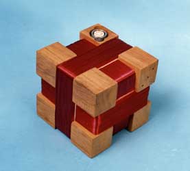
The sensor on the left has the three coils centred on each other. They are air-cored, and to get the necessary sensitivity, they have thousands of turns of wire. These examples are 10 cm square.
The sensor on the right has much smaller coils to make a smaller overall meter. To get the sensitivity despite the smaller size, the coils have iron cores. This means they cannot be centred on the same point; they are arranged separately, at right angles to each other (two are flat on the pcb at the bottom left, the third, vertical, coil is provided with a white mechanical support at the bottom right).
(e) Readout and logging. Meters may have analogue or digital displays. They may only display a value in real time, or they may be capable of logging values with various degrees of sophistication, and of calculating various parameters of the field such as averages or maxima.
Given the variations in facilities provided by a meter, there is an inevitable variation in size, weight, and battery consumption. Some meters are most suitable for detailed surveys by experts; others are small and light enough to be worn by volunteers for extended periods.
There is no “correct” or “best” meter. The best meter to use depends on the purpose it is to be used for.
Measuring magnetic fields
There are three different sensors widely used for measuring magnetic fields:
(a) Search coils. The simplest meters measure the voltage induced in a coil of wire. For a sinusoidally varying magnetic field, B, of frequency f, the voltage, V, induced in the coil is given by:
V=-2 π f B 0A cos(ω t)
where ω = 2 π f is the frequency of the field and A is the area of the loop, and B0 is the component of B perpendicular to the loop.
The voltage induced by a given field increases with the addition of more turns of wire or of a ferromagnetic core - see the examples above. To prevent interference from electric fields, the magnetic field probe must be shielded. If the meter is used for surveys or personal exposure measurements, frequencies lower than approximately 30 Hz must be filtered out to remove voltages induced in the probe by the motion of the meter in the earth’s magnetic field.
(b) Fluxgate magnetometers. These detect a magnetic field by the asymmetry it produces in a ferromagnetic material deliberately driven in magnetic saturation alternately in opposite directions at a high frequency.
(c) Hall-effect devices. The sensor is designed to measure the transverse Hall voltage across a thin strip of semiconducting material carrying a longitudinal current.
Most practical instruments for power frequencies use search coils, either a single coil or three orthogonal coils. The coils themselves can either be made as small as possible, with a ferromagnetic core to increase sensitivity, for use in personal exposure meters where size and weight are important criteria; or they can be larger, often 0.1 m across, to increase sensitivity and provide some spatial averaging. Fluxgate magnetometers cannot be made as small or as cheap, but have the advantage of responding to dc fields as well as ac. Hall devices are little used as their resolution is poorer and they suffer from drift but have uses at higher fields.
Measuring electric fields
Meters for electric fields usually use as sensors two parallel conducting plates. Alternative sensors, e.g. based on rotation of polarised light, are less common.
Three-axis electric-field meters are available, but single-axis meters are more common. This is partly because it is harder to make three-axis meters for electric fields than for magnetic fields, and partly because in one common measuring situation, near ground underneath or close to overhead power lines, the electric field is linearly polarised and in a known direction (vertical), and therefore a single-axis meter is perfectly sufficient.
A person holding an electric-field meter would perturb the field. To measure the unperturbed field, the meter is usually suspended at the end of a long non-conductive horizontal rod or vertical tripod. The reading is read from a distance on a suitably sized display, recorded within the meter for later analysis, or transmitted to a readout device by fibre-optic. This can reduce perturbation to acceptable levels. However, given the ease of perturbation of electric fields, it is easy to make erroneous measurements, particularly when there is:
- extremes of temperature and humidity;
- insufficient distance of the probe from the investigator;
- instability in meter position;
- loss of non-conductive properties of the supporting rod.
Electric fields can also be measured at fixed locations, e.g. under transmission lines or in laboratory exposure chambers by measuring the current collected by a flat conducting plate placed at ground level. For sinusoidal fields, the electric flux density can be calculated from the area of the plate (A), the permittivity of a vacuum , the frequency (f) and the measured current induced in the plate in the expression below:
E=Irms/2πfε0A
Personal exposure meters do exist for electric fields. However, wearing a meter on the body, perturbs the electric field being measured in unpredictable ways. Typically, where exposure to electric fields of large groups of subjects is being measured, a meter is placed in an armband, shirt pocket or belt pouch. Perturbation of the ambient field by the body precludes obtaining an absolute value of the field and, at best, the average value of such measurements reflects the relative level of exposure.
Standards for measurement of electric and magnetic fields
IEC
The following standsrds have been produced by the International Electrotechnical Commission (IEC):
| Reference | Title |
|---|---|
| IEC 61786-1:2013 | Measurement of DC magnetic, AC magnetic and AC electric fields from 1 Hz to 100 kHz with regard to exposure of human beings - Part 1: Requirements for measuring instruments |
| IEC 61786-2:2014 | Measurement of DC magnetic, AC magnetic and AC electric fields from 1 Hz to 100 kHz with regard to exposure of human beings - Part 2: Basic standard for measurements |
| IEC 62110:2009 | Electric and magnetic field levels generated by AC power systems - Measurement procedures with regard to public exposure |
| IEC 62110:2009/COR1:2015 | Corrigendum 1 - Electric and magnetic field levels generated by AC power systems - Measurement procedures with regard to public exposure |
| IEC 62226-1:2004 | Exposure to electric or magnetic fields in the low and intermediate frequency range - Methods for calculating the current density and internal electric field induced in the human body - Part 1: General |
| IEC 62226-2-1:2004 | Exposure to electric or magnetic fields in the low and intermediate frequency range - Methods for calculating the current density and internal electric field induced in the human body - Part 2-1: Exposure to magnetic fields - 2D models |
| IEC 62226-3-1:2007+AMD1:2016 CSV | Exposure to electric or magnetic fields in the low and intermediatefrequency range - Methods for calculating the current density and internal electric field induced in the human body - Part 3-1: Exposure to electric fields - Analytical and 2D numerical models |
| IEC 62226-3-1:2007 | Exposure to electric or magnetic fields in the low and intermediate frequency range - Methods for calculating the current density and internal electric field induced in the human body - Part 3-1: Exposure to electric fields - Analytical and 2D numerical models |
| IEC 62226-3-1:2007/AMD1:2016 | Amendment 1 - Exposure to electric or magnetic fields in the low and intermediate frequency range - Methods for calculating the current density and internal electric field induced in the human body - Part 3-1: Exposure to electric fields - Analytical and 2D numerical models |
| IEC 62233:2005 | Measurement methods for electromagnetic fields of household appliances and similar apparatus with regard to human exposure |
| IEC 62311:2007 | Assessment of electronic and electrical equipment related to human exposure restrictions for electromagnetic fields (0 Hz - 300 GHz) |
| IEC TR 62630:2010 | Guidance for evaluating exposure from multiple electromagnetic sources |
| IEC TR 62669:2011 | Case studies supporting IEC 62232 - Determination of RF field strength and SAR in the vicinity of radiocommunication base stations for the purpose of evaluating human exposure |
These standards are produced by Technical Committee 106. TC106 also produce many other standards that relate to radiofrequencies.
CENELEC
The following standards have been produced by the CENELEC, the European Electrical Standards body:
| Reference | Title |
|---|---|
| EN 50413: 2008 | Basic standard on measurement and calculation procedures for human exposure to electric, magnetic and electromagnetic fields (0 Hz - 300 GHz) |
| EN 50647: 2017 | Basic standard for the evaluation of workers' exposure to electric and magnetic fields from equipment and installations for the production, transmission and distribution of electricity |
These standards are produced by Technical Committee 106X. TC106X also produce many other standards that relate to radiofrequencies.
Calculating magnetic fields
Calculating magnetic fields
If you know that there is one dominant source of EMFs present it is often possible to calculate the fields it produces. Overhead lines and underground cables lend themselves to this. It is possible for substations too, but harder because the geometry is more complicated. You can't easily do calculations for low-voltage distribution sources because you don't normally know the currents accurately enough.
Download a step-by-step tutorial on how you would go about calculating the magnetic field from a simple three-phase circuit: How to calculate the magnetic field.pdf. Or a similar one for DC cables: How to calculate the magnetic field DC.pdf. Calculating electric fields is harder - see the next toggle for an explanation of why.
Calculations are often preferable to measurements because you can perform them for any desired conditions rather than being limited to the particular conditions at the time you do the measurement.
Calculations can be as accurate as you like. You can see a comparison of calculations and measurements from an overhead line and here for a discussion of how accurate the calculations can be.
Calculations (and measurements) are often performed at 1 m above ground because this is the relevant height for assessing the induced current in a person.
For power lines and cables, calculations usually assume the conductors are infinite straight lines. But see details of the effect that modelling the sag of the conductors has (usually quite a small effect, which is why it's not usually done) and see what happens when the conductors are only finite length.
We offer an on-line calculator for the magnetic fields from some of the standard UK overhead lines.
Calculating electric fields
In the previous toggle, we explained that you can only usually calculate magnetic fields for overhead lines and underground cables with defined geometries and known currents.
The same thing applies for electric fields - you can only easily calculate for situations where there's a nicely defined geometry and known voltages - but there are two extra complications.
The first is that electric fields are easily perturbed by conducting objects. So the calculation needs to take account of trees, fences, undulations in the ground, buildings, etc. That can't be done with simple formulas - it needs numerical calculations, and an awful lot of setting up.
The second is that, even when we're calculating for a known geometry (a power line) with no perturbations (flat unobstructed ground), the calculation itself is more complicated. With magnetic fields, the field is produced by the current, and we know the current. With electric fields, the field is produced by the charges on the conductors, but we don't know the charges. What we know is the voltage. The charge is related to the voltage by capacitances - the capacitance of every conductor to every other conductor. So we can work out the charges, and hence calculate the electric field, but it's more complicated. We have to create a matrix of the capacitance of every conductor to every other conductor. That would tell us the voltages from the charges. But we want to do it the other way round - start with the voltages and calculate the charges. We can do that by inverting the matrix (and inverting large matrices is emphatically not something you want to do by hand).
So the sequence is: Create the capacitance matrix. Invert it. Use the inverse matrix and the voltages to calculate the charges. Then use the charges to calculate the fields.
That is perfectly do-able, and bespoke EMF calculation software packages do exactly that. We use such a package to calculate the electric fields we give for all the various voltages of overhead line. But it's more complicated than calculating magnetic fields (and sorry, for the moment, the online calculator that we provide only does magnetic fields).
There's a further subtlety with electric fields. The ground is conducting and perturbs the field itself. The good news is, that's a perturbation we can model quite easily. The effect is exactly as if there was a set of "image charges" below the ground, with the ground as the symmetry plane between the actual charges on the overhead line above ground and the image charges below ground. So we can calculate the field taking account of the ground my modeling the combined effect of both sets of conductors. The bad news is, with twice as many conductors to include, the calculation is at least twice as complicated...