Electric fields are easily screened. Anything that is even slightly conducting will have a screening effect. That is why houses screen the field inside them and trees, fences etc can provide screening as well, as they are all sufficiently conducting for this purpose. Metal, of course, is a good conductor and provides excellent screening. The electric field inside a closed metal box is basically zero. This is called a Faraday Cage. In practice, electric field screens are an approximation to this closed box. If the screen is grounded, the earth itself is included in the screen.
Magnetic fields are much harder to screen. There are two ways of doing it. One is to use “high permeability” alloys, known as "ferromagnetic screening". The best known of these is mu-metal, but this is expensive and difficult to work with. The other is to use a conducting screen such as aluminium or conductive loops, known as "induced current screening". The magnetic field induces currents in this which generate their own magnetic field which partially cancels the original field. But this usually requires quite thick metal plates to be effective.
Screening magnetic fields is never an easy option. In UK practice, once the fields from an overhead line or underground cable were below the relevant exposure limits, there would not be sufficient reason to reduce the fields further by screening, unless there was a very specific reason, such as sensitive equipment in a hospital, or aircraft, where there might be a risk of interference.
Various devices are available to purchase which claim to reduce EMF exposure. Further information about these devices can be found here
Ferromagnetic screening
Consider a set of conductors - probably the conductors that make up an underground cable enclosed within a tube that forms the screen.
The cables, inside the tube, still produce basically the same magnetic field. The magnetic field lines start by extending out from the cables in much the same way as if there were no screening. When they reach the tube, however, most of the field lines get “trapped” or “sucked into” the metal of the tube, and instead of carrying on further away from the cables, they bend round inside the thickness of the tube. Only a few field lines “escape” from the tube or extend outside it. Hence the field outside the tube is considerably reduced.
The effectiveness of the tube depends on the magnetic properties of the tube material. Specifically, the tube needs to be ferromagnetic. Ferromagnetic materials are defined by a property called the “relative permeability”, abbreviated µr. The higher the relative permeability, the more effective the screening. But the relative permeability of steels is a fairly variable parameter, depending on the carbon content, and, to some extent, on the manufacturing process. Mu metal is a particular alloy developed to have very high relative permeability and therefore to be a good screen, but it is quite difficult to work.
Even if the material properties are known, it is quite difficult to calculate the effect of the screening exactly. Equations can be set up and solved for relatively simple geometries with high degrees of symmetry. In practice, however, it is usual to perform a numerical calculation.
Note that the screen has to surround all the conductors at once. It doesn't work if it only goes round a single conductor.
Instead of screening the source of the field, you can screen a specific volume where you want to reduce the field. The same principle applies: the field gets sucked into the screen and therefore diverted out of the volume in question.
Ferromagnetic screening - practical examples
Screening of cables is not something undertaken lightly. It requires a substantial amount of metal in the screen, it makes laying the cable more difficult, and it can reduce the rating of the cable by making it harder for the heat produced in the cable to conduct away. It is not normally necessary in the UK, because UK cables comply with the relevant exposure limits without any screen, so there is no legal or regulatory basis for incurring extra expense to reduce the field further.
Screening AC cables in Italy
Ferromagnetic screening has been done in at least some places in Italy, to achieve compliance with the more restrictive exposure limits there. See the following pictures:
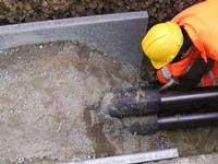 Open trough made from high-permeability steel with three cables being laid inside
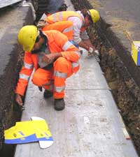 Trough after the lid is attached to provide continuous screening all round the cables
Photos of Turbigo-Rho single circuit 380 kV transmission line, owner: Terna, manufacturer: Prysmian, courtesy of Terna
Screening DC cable in the UK
Although screening of cables in the UK is not normally needed, there is one example where cables cross an airfield, and there is a need to reduce the fields to avoid interference with aircraft navigation and avionics. The DC cables will be installed inside a steel tube to reduce the fields.
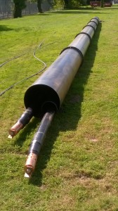
DC cables inside steel screening tube, laid out in demonstration at ground level
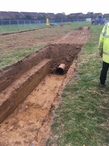
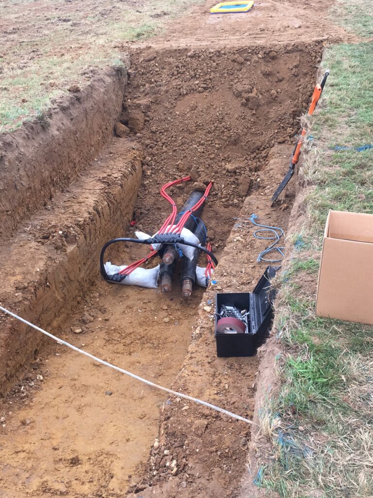
Sample length of creened cable being buried for testing
Induced current screening
Let's say we have a source of field - an underground cable or overhead line. This produces a magnetic field. We arrange a loop of conductor so that some of this field passes through the loop. Because it's an alternating field, it induces a current in the loop, and that current in turn produces its own field - which, if we've got the design right, just happens to be in the opposite direction to the field from the source we're trying to screen, so backs off some of that field, reducing the field strength.
With conducting sheets instead of an actual loop, the principle is exactly the same. Think of the sheet as making up a continuous array of loops joined together. It can be more efficient, because the induced current can find its optimum path around the sheet, but of course it involves more material.
Induced current screening - practical examples
There are quite a few examples around the world where cables or overhead lines have been screened, either to comply with exposure limits in countries that have more onerous limits, or to reduce the field in particularly sensitive places, such as in hospitals or universities where there is the risk of interference with sensitive equipment.
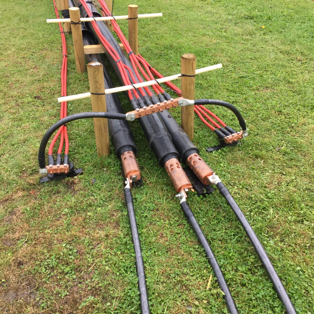
This picture shows a trial (at ground level, prior to burying it) of screening AC cables. The three black cables are the transmission circuit that is the source of the field. Each pair of bundles of red cables, joined together at the ends, form a screening loop, making four separate loops altogether.
Induced current screening - more detail on the physics
Why is the induced field in the opposite direction to the source field?
The source field, passing through the screening loop, induces a voltage. By the laws of electromagnetic induction, that voltage is 90 degrees out of phase with the inducing field.
Then, if the screening loop is purely inductive - negligible resistance - the current induced is a further 90 degrees out of phase with the voltage.
Those two 90 degree phase shifts add up to 180 degrees, making the field from the screening loop exactly opposite in phase to the source field, just what we need for it to cancel the source field.
What does it take to make the screening as effective as possible?
In most practical situations, the screening loop has to be a little way away from the source conductors, so is not perfectly coupled to the field, so the current induced isn't as large as we'd like. To increase the current in the screening loop, we want to reduce its self inductance. We can do that to some extent by using fatter conductors (or using bundles of smaller conductors), but if we care enough about improving the efficiency of the screening, we can also insert capacitors in the screening loop (in electrical engineering terms, capacitance is the opposite of inductance - the capacitance of the capacitors cancels the inductance of the loop).
Of course, adding capacitors increases the complexity and cost. It moves away from the inherent simplicity of a loop of wire and introduces something that will need inspection and maintenance. But it's an option if the need to reduce fields is strong enough.
What is the limit on how effective the screening can be?
If we reduce the inductance by using capacitors, and if we move the screening loop as close as possible to the source to increase the coupling, we will still have two limits on the effectiveness. One is that the resistance of the screening loop will start to become significant, and there's probably a practical limit to how far we can reduce that by using bigger conductors. The other is that the source field is likely to be elliptically polarised, but the screening loop only screens the component of the field perpendicular to the loop. The bit of the elliptical polarisation that is parallel to the loop won't be screened.
Active screening
We talked above about what we can do to the design of a passive screening loop to make the screening as effective as possible. If that's not good enough, there's an option to drive the current in the screening loop actively, from our own power source, so that it's exactly the optimum current, rather than relying on passive induction.
This would normally be used only where there was a very specific volume that needed screening for a particular reason. Then you would use a sensor to measure the field, and some electronics in a control circuit to drive exactly the right current in the loop to reduce that field to a minimum.
We've heard of this being done to screen a particular room, but never on a large scale, and it doesn't really work for screening the field from a source over a large area.